
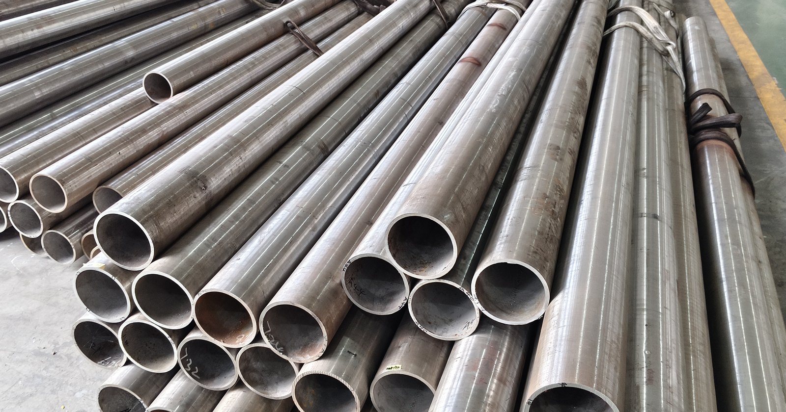
Cold drawn seamless (CDS) tube is the specification most engineers write and the fewest buyers can actually verify. This guide connects the standard, the delivery condition, the tolerance and the inspection document into one decision path, so that what arrives on site matches what was quoted.
Most enquiries we receive start the same way: a drawing, a grade designation, and a tolerance that may or may not be achievable at that size. The gap between what a purchase order says and what a mill can deliver is almost always created at the specification stage, not at production. The sections below are ordered to close that gap.
1. What cold drawn seamless tube actually is
CDS tube begins as a hot finished seamless mother tube, produced by piercing and rolling a solid billet. That hollow shell has the right chemistry but poor dimensional control: outer diameter typically varies by ±1% or more, wall eccentricity is significant, and the surface carries mill scale. Cold drawing is the correction step.
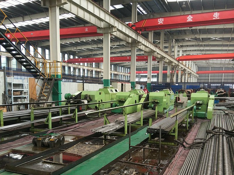
The process chain runs: hot finished shell, pickling and phosphating to remove scale and provide a lubricant carrier, cold drawing through a die, heat treatment, straightening, and cutting. Drawing may repeat two or three times depending on the reduction required, with an anneal between passes to restore ductility.
Two drawing methods matter commercially, because they produce different products:
- Plug drawing (mandrel drawing) — a fixed plug or mandrel sits inside the tube while it is pulled through the die. Both the outer diameter and the wall are controlled. Wall thickness is reduced in a predictable way, and concentricity improves. This is what most precision CDS tube is made by.
- Sinking (empty drawing) — no internal tool. Only the outer diameter is reduced; the wall thickens by roughly the volume relationship and eccentricity is not corrected. Cheaper and faster, but unsuitable where wall tolerance or bore quality is specified.
The reason cold drawing delivers tolerances hot rolling cannot is not the die alone. It is the combination of a small reduction per pass, a controlled die angle, and the work hardening that freezes the geometry in place. Cold work raises yield strength substantially, which is why the final heat treatment is not optional. It is what determines whether the tube is delivered hard, stress relieved, annealed or normalised, and that choice is where most specification errors occur. Section 5 deals with it in detail.
2. CDS, DOM and hot-rolled seamless are three different products
These three are routinely quoted against each other as if they were interchangeable. They are not, and the difference starts at the mother tube.
| Attribute | CDS (cold drawn seamless) | DOM (drawn over mandrel) | Hot-rolled seamless |
|---|---|---|---|
| Mother tube | Hot pierced seamless shell | ERW welded strip | Hot pierced shell, as-rolled |
| Weld seam | None | Present, normalised after drawing | None |
| Typical OD tolerance | ±0.05 to ±0.10 mm | ±0.05 to ±0.13 mm | ±0.5% to ±1% |
| Wall tolerance | ±5% to ±10% | ±5% to ±10%, more uniform around circumference | ±10% to ±12.5% |
| Bore condition | Good; can be honed or roller burnished | Very good as-drawn | Mill scale, requires machining |
| Pressure and fatigue | Best; no seam to initiate failure | Adequate for many duties; seam remains a metallurgical discontinuity | Good, but thick wall and coarse tolerances |
| Cost at volume | Higher | Lower | Lowest |
| Practical size range | 6 to 380 mm OD | Approximately 12 to 150 mm OD | Up to 700 mm OD and beyond |
| Typical use | Hydraulic cylinders, precision shafts, heat exchanger tubes, fuel injection | Automotive shock absorbers, gas springs, general mechanical tube | Line pipe, structural, boiler and pressure service |
Tolerance values are typical commercial capability, not standard requirements. Actual limits depend on size, wall ratio and delivery condition.
The commercial logic is often inverted in procurement. DOM is frequently described as the premium option because it is dimensionally excellent and costs less, but DOM is a welded product. Drawing over a mandrel and normalising restores mechanical properties close to the parent metal, yet the weld line remains detectable metallographically and behaves differently under cyclic loading and in corrosive service. For hydraulic cylinders, high-pressure circuits and anything subject to fatigue, CDS is the correct default. For a shock absorber reservoir running at moderate pressure, DOM is the rational choice and specifying CDS simply raises cost without adding service life.
A related confusion is cold drawn versus cold rolled. Cold rolling is used for strip and sheet, and for welded tube made from cold rolled coil. Seamless tube is drawn, not rolled. If a drawing specifies “cold rolled seamless tube”, the requirement is ambiguous and should be clarified before quoting. Our own note on hot rolled versus cold rolled seamless pipe covers the process distinction in more detail.
3. The standards map: which specification actually applies
The EN 10305 family alone has six parts, and alongside DIN 2391, ASTM A519, GB/T 3639 and JIS G3445 they cover most CDS enquiries worldwide. They are not ranked by quality. They describe different scopes, and choosing the wrong one produces a tube that is correct to a standard nobody asked for.
| Standard | Scope | Principal grades | Typical OD range | Delivery conditions | Common market |
|---|---|---|---|---|---|
| EN 10305-1 | Seamless cold drawn precision tubes, circular section | E215, E235, E255, E355, E410, 26Mn5, C35E, C45E, 25CrMo4, 42CrMo4 | Up to 380 mm | +C, +LC, +SR, +A, +N | EU, Middle East, Asia, South America |
| EN 10305-2 | Welded cold drawn circular precision tubes | E195, E235, E275, E355 | Up to 150 mm | +C, +LC, +SR, +A, +N | EU |
| EN 10305-3 | Welded cold sized precision tubes. The 2023 edition absorbed the former Part 5 shaped-tube scope | E195, E235, E275, E355 | Up to 150 mm round | +C, +LC, +SR, +A, +N | EU |
| EN 10305-4 | Seamless cold drawn tubes for hydraulic and pneumatic power systems | E215, E235, E355 | Up to 168.3 mm | +C, +LC, +SR, +A, +N (+N is the default) | EU, hydraulic OEMs globally |
| EN 10305-6 | Welded cold drawn tubes for hydraulic and pneumatic power systems | E235, E355 | Up to 168.3 mm | +C, +LC, +SR, +A, +N | EU |
| DIN 2391 | Seamless precision steel tubes. Withdrawn and superseded by EN 10305-1 | St30.4, St35.4, St52.4 | Up to 380 mm | BK, BKW, BKS, GBK, NBK | Legacy German drawings, Eastern Europe, Turkey, Iran |
| ASTM A519 | Seamless carbon and alloy steel mechanical tubing | 1010, 1018, 1020, 1026, 1035, 1045, 4130, 4140, 4145, 8620 | Up to 300 mm | As-rolled, cold drawn, annealed, normalised, stress relieved, Q&T | North America, export to US-spec projects |
| GB/T 3639 | Cold drawn or cold rolled precision seamless steel tubes (China) | 10, 20, 35, 45, 40Cr, 20CrMnTi | Up to 200 mm | Cold drawn hard, annealed, normalised | China domestic, some Asian projects |
| JIS G3445 | Carbon steel tubes for machine structural purposes | STKM 11A to 18C | Up to 200 mm | As-drawn, annealed, normalised | Japan, Southeast Asia |
3.1 DIN 2391 and EN 10305-1: the substitution trap
DIN 2391 was withdrawn in the 1990s and replaced by EN 10305-1. Two decades later, a large share of drawings in circulation still cite it. This is not a problem in itself, since the technical content is largely inherited, but it creates three specific failure modes.
Grade names do not survive translation automatically. St30.4 maps to E215, St35.4 to E235, St52.4 to E355. A supplier who reads “St52.4” and quotes E355 is correct. A supplier who reads it as a plain carbon steel and quotes something equivalent to S355 structural tube is not, and the paperwork will look plausible until a tensile test is compared against the certificate.
Condition suffixes differ between the systems. DIN uses BK, BKW, BKS, GBK, NBK. EN uses +C, +LC, +SR, +A, +N. They correspond one to one, but a drawing that says “DIN 2391/C” is using yet another notation, where C means cold drawn hard, equivalent to +C. Three naming conventions for one requirement is a reliable source of mismatch. Our DIN 2391 specification reference sets out the full mapping.
The dimensional clauses are not identical. DIN 2391-1 and EN 10305-1 each carry their own tolerance tables, and the numbers do not coincide. EN 10305-1 gives absolute outside diameter tolerances by size band: ±0.08 mm for 4 to 30 mm, ±0.15 mm for 30 to 40 mm, ±0.20 mm for 40 to 50 mm, ±0.25 mm for 50 to 60 mm, ±0.30 mm for 60 to 70 mm, and ±0.35 mm for 70 to 80 mm, with wall tolerance of ±10% subject to a 0.1 mm minimum. A tube that met DIN 2391-1 dimensional requirements is therefore not automatically compliant with an EN 10305-1 order, and the divergence is largest in the small size bands where most hydraulic work sits. This is the single most common source of rejection on legacy drawings we see.
A third system is often confused with both. The tolerance classes of EN ISO 1127, designated D1 to D4 for outside diameter and T1 to T5 for wall, are used for stainless tube and for DIN 2642 callouts. They are not the EN 10305-1 tables. A drawing that cites a D or T class against a carbon steel precision tube is mixing two systems and should be clarified before quotation.
Practical rule. When a drawing cites DIN 2391, the purchase order should carry both designations and the actual tolerance values: for example, “EN 10305-1:2016, grade E355 (St52.4 equivalent), delivery condition +SR, dimensions and tolerances to EN 10305-1 with the values confirmed in writing, dimensional equivalence to DIN 2391-1 confirmed by the supplier.” That sentence removes the ambiguity that causes most disputes.
3.2 Choosing between EN 10305-1, -3 and -4
EN 10305-4 is frequently requested as though it were an upgraded version of -1. It is not. Part 4 applies to seamless cold drawn tube for hydraulic and pneumatic power systems, and it adds requirements that part 1 does not: tighter control of the bore, defined cleanliness, and pressure integrity testing appropriate to the circuit. A -4 tube and a -1 tube of the same grade and dimensions are different products with different inspection scope.
The delivery conditions are the same five, but the standard treats +N as the default for fluid power tube, and that is not an arbitrary choice. Normalising restores ductility, which is what allows the tube to be bent, flared and formed at the assembly stage without cracking. For hydraulic piping, part 4 in condition +N is the standard combination. For cylinder barrels that will be honed after delivery, +SR is often specified instead, because dimensional stability under machining matters more there than bendability.
EN 10305-3 is the trap of a different kind. It covers welded cold sized tube. Buyers specify it believing the “precision” of the title implies seamless construction. It does not. If the application requires no seam, part 1 or part 4 is the correct reference.
For hydraulic cylinder barrels and piston rods, part 4 with condition +SR and a honed or roller burnished bore is the standard combination. For general precision mechanical work, part 1 is the right and cheaper answer. Our product pages for EN 10305-1 seamless tube and EN 10305-4 hydraulic tube set out the available size and condition combinations.
3.3 Where ASTM A519 fits
ASTM A519 is a mechanical tubing specification, not a precision tube specification in the European sense. Its grades are AISI/SAE designations rather than the E series, and its condition list includes quenched and tempered, which EN 10305-1 does not offer. This makes A519 the natural choice for machined components requiring through-hardening, such as 4140 or 4145 hollow bar for rings, rollers and shafting.
The two systems are not interchangeable grade by grade. 1026 and E355 sit in a similar carbon-manganese range but differ in specified limits, tolerances and test frequency. A substitution must be justified by property, not by composition alone, and the certificate must be issued against the standard actually ordered.
4. Grades and the mechanical values that drive selection
Grade selection is usually driven by three numbers: minimum yield, tensile range, and elongation after fracture. The table below gives the EN 10305-1 values in the two conditions most often quoted, stress relieved and normalised, alongside the withdrawn DIN designation.
| EN grade | DIN 2391 | Steel no. | +SR: ReH / Rm / A | +N: ReH / Rm / A | Typical application |
|---|---|---|---|---|---|
| E215 | St30.4 | 1.0212 | 280 MPa / 380 MPa / 16% | 215 MPa / 290–430 MPa / 30% | Light mechanical, furniture, general engineering |
| E235 | St35.4 | 1.0308 | 350 MPa / 420 MPa / 16% | 235 MPa / 340–480 MPa / 25% | Hydraulic lines, general precision components |
| E255 | — | 1.0408 | 375 MPa / 520 MPa / 12% | 255 MPa / 440–570 MPa / 21% | Higher strength mechanical tube |
| E355 | St52.4 | 1.0580 | 450 MPa / 580 MPa / 10% | 355 MPa / 490–630 MPa / 22% | Cylinder barrels, structural precision, piston tubes |
| E410 | — | 1.0509 | 590 MPa / 690 MPa / 12% | 410 MPa / 550–700 MPa / 22% | High strength mechanical, mining |
| C45E | — | 1.1191 | — | 340 MPa / 540 min / 18% | Machined parts requiring hardness after heat treatment |
| 25CrMo4 | — | 1.7218 | — | — | Quench and temper applications, hollow bar |
| 42CrMo4 | — | 1.7225 | — | — | High strength shafts, gears, rings |
ReH and Rm in MPa, A in percent. Minimum values per EN 10305-1:2016 for the specified condition. For tubes with OD ≤ 30 mm and wall ≤ 3 mm, minimum ReH in condition +N is 10 MPa lower than the tabulated figure. Alloy grades are normally ordered in the quenched and tempered condition rather than +SR or +N.
Two practical observations. First, the +C condition produces the highest strength and lowest elongation, and designers who read only the +C column often over-specify: a tube at Rm 640 MPa with 4% elongation is unsuitable for any operation involving bending or expansion. Second, a higher grade is not automatically a safer choice. E355 in +C condition machined without stress relief will move after the first cut, because the internal stress locked in by drawing is released unevenly. The dimensional accuracy that made CDS attractive disappears at the machining centre.
5. Delivery conditions: what +C, +LC, +SR, +A and +N change
The delivery condition is the most under-specified line on a CDS purchase order and the one that determines whether the tube can be fabricated at all. It describes the final thermal treatment after the last drawing pass.
| EN symbol | DIN symbol | Meaning | Strength | Ductility | Dimensional stability after machining | Weldability |
|---|---|---|---|---|---|---|
| +C | BK | Cold drawn, hard. No heat treatment after final drawing. | Highest | Lowest | Poor: residual stress releases on cutting | Not recommended |
| +LC | BKW | Cold drawn, soft. Final light drawing pass after heat treatment. | High | Moderate | Moderate | Limited |
| +SR | BKS | Cold drawn and stress relieved in controlled atmosphere. | Moderate to high | Good | Good | Yes, with procedure |
| +A | GBK | Soft annealed after final drawing. | Lowest | Highest | Good | Yes |
| +N | NBK | Normalised after final drawing. | Moderate | Good | Good | Yes |
5.1 Matching condition to the next operation
This is the decision most often made by default rather than by design. The correct approach is to start from the first operation performed after delivery.
| Next operation | Recommended condition | Reason | If the wrong condition is used |
|---|---|---|---|
| Turning, milling, drilling only | +C or +SR | +C gives highest strength and best as-drawn surface for light cuts; +SR if dimensional stability is critical | +C machined thin-wall parts distort after stress release |
| Welding to end fittings or flanges | +SR or +N | Low residual stress and adequate ductility in the heat affected zone | +C welded: hard HAZ plus locked-in stress, delayed cracking days after welding |
| Bending, flaring, expansion | +A or +N | Elongation available to accommodate outer fibre strain | +C or +LC: cracking on the outside radius, ovality beyond limit |
| Honing or roller burnishing the bore | +SR | Stable dimensions and predictable material removal | +C: bore distorts as stress redistributes during honing |
| Subsequent hardening and tempering | +N | Uniform starting microstructure gives repeatable response to austenitising | +C: inherited cold work causes uneven grain growth and distortion |
| Deep drawing or cold forming | +A | Maximum elongation, minimum yield | +C or +SR: fracture at the first forming pass |
| No further operation, used as delivered | +C or +SR | Condition is the service condition | +A: insufficient strength for the duty |
The expensive mistake. Specifying +C because it is cheaper and then welding the tube into an assembly. Cold drawing leaves a through-thickness residual stress pattern plus a work hardened structure. Welding adds thermal stress on top. The result is a heat affected zone harder than the parent metal, sitting in a tensile stress field, which is the classic condition for hydrogen assisted delayed cracking. Failure typically appears 24 to 72 hours after welding, often during pressure testing, and is frequently misdiagnosed as a material defect. A related failure mode in cold drawn tube that has seen subsequent thermal processing is examined in our case study on ring-shaped hole defects in 34CrMo4 accumulator tube.
6. Tolerances you can actually hold
Tolerance is where quotations diverge most. A supplier quoting ±0.05 mm on a 90 mm tube and one quoting ±0.15 mm may both be describing their true capability, because the achievable limit is a function of size and wall ratio, not a single number.
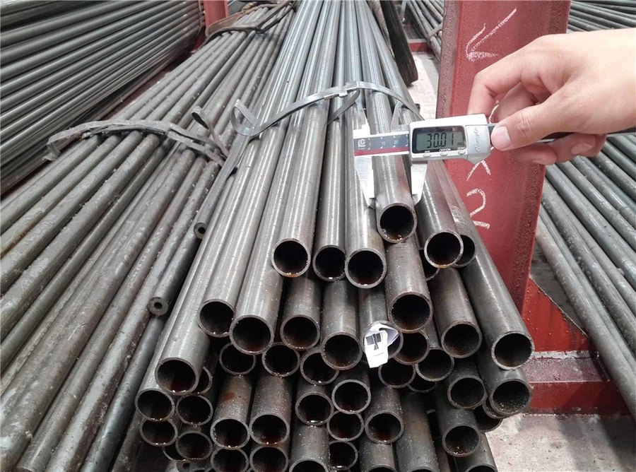
Before the table, one distinction that causes more disputes than any other. The tolerance the standard requires and the tolerance a mill can hold are different numbers. EN 10305-1 itself requires ±0.08 mm on 4 to 30 mm OD and progressively looser bands up to ±0.35 mm at 70 to 80 mm. Anything tighter than the standard figure is a negotiated capability, not a compliance requirement, and should be written into the order as an agreed value rather than inferred from the standard reference.
| Parameter | Standard commercial | Precision capability | Conditions required for the precision figure |
|---|---|---|---|
| Outside diameter | ±0.10 mm | ±0.05 mm | OD below 30 mm, wall/OD ratio above 6%, plug drawn, +SR or +A |
| Outside diameter, larger sizes | ±0.15 mm | ±0.10 mm | OD 30 to 90 mm; beyond 90 mm ±0.15 mm is realistic |
| Wall thickness | ±10% | ±5% | Plug drawn with mandrel; eccentricity controlled at mother tube stage |
| Inside diameter, honed | H10 | H8 | Honing after stress relief; bore diameter above 30 mm for H8 |
| Straightness | 1 : 1000 | 0.5 mm per metre | Rotary straightening plus stress relief; measured mid-length |
| Ovality | 80% of OD tolerance | 50% of OD tolerance | Final sizing pass; degrades if tube is re-handled without support |
| Length, exact | +10 / 0 mm | ±1 mm | Cold saw or band saw with stop; deburred both ends |
| Surface roughness, bore | Ra 1.6 µm | Ra 0.4 µm | Honed, cross-hatch 30 to 45 degrees, or roller burnished |
| Concentricity | Not normally specified | 0.5 × wall tolerance | Mandrel drawing, wall ratio above 8% |
Capability figures represent what production cold drawing holds routinely without selection or extra operations. Values outside these ranges are achievable by negotiation but should be treated as a separate process, not as a tolerance on a standard order.
Three statements in this table deserve emphasis because they are the ones most often over-promised.
±0.05 mm is a small-size figure. It holds on thin wall tube under about 30 mm OD, where the die can control the section effectively. Asking for ±0.05 mm on a 120 mm OD, 8 mm wall tube is asking for a different manufacturing route, and the quotation will either be wrong or unrealistically high. If wall thickness must also be pressurised or machined, the practical limit moves toward ±0.10 mm.
Wall tolerance is a percentage, not an absolute. ±5% on a 3 mm wall is ±0.15 mm. On a 12 mm wall it is ±0.60 mm. Buyers who convert a percentage into a fixed millimetre figure and then apply it across a size range usually find that half their list is outside capability. Where wall uniformity genuinely matters, the correct specification is eccentricity or concentricity, not a tighter wall percentage. Wall thickness selection itself is covered in our note on wall thickness and pressure resistance calculation.
Straightness depends on how it is measured. One millimetre per metre measured over the full length and 0.5 mm per metre measured at mid-span are not the same requirement. State the measurement method, or expect the argument at goods receipt.
7. Surface, bore condition and cleanliness
Surface specification is often reduced to a single word on the order, which leaves the actual condition to the mill’s default. The options that matter commercially are these.
- Pickled — oxide scale removed by acid. The minimum acceptable condition for any tube that will be inspected visually or coated. Pickled tube has a grey, matte finish and will flash rust without protection.
- Phosphated — a conversion coating applied as a drawing lubricant carrier. Useful if the customer will draw or cold form the tube again; neutral to most other operations.
- Oiled — rust preventive applied after pickling or phosphating. Standard for export. Specify oil type if the tube will be welded without cleaning, since some proprietary oils leave residue that causes porosity.
- Honed bore — internal grinding with a reciprocating head, producing a controlled Ra and a cross-hatch pattern that retains lubricant. Standard for hydraulic cylinder barrels. Ra 0.4 µm with 30 to 45 degree cross-hatch is the usual requirement; Ra 0.2 µm is achievable but adds cost and inspection time.
- Roller burnished (SRB) bore — the bore is plastically smoothed by rolling rather than cut. Produces a very fine finish and a work hardened surface layer. Faster and cheaper than honing, but does not correct bore geometry, so it cannot rescue an out-of-round tube.
For hydraulic service, cleanliness is a separate requirement from roughness. Residual drawing lubricant, phosphate dust and cutting debris inside a tube will contaminate the circuit and damage pumps. A tube can meet its dimensional specification and still fail at commissioning for this reason. Degreasing and passivation practice is set out in our note on degreasing, cleaning and passivation of seamless tube, and for EN 10305-4 orders the cleanliness requirement should be stated explicitly rather than assumed.
8. Inspection, testing and documentation
The inspection document is the part of the order that survives longest. It will be read by the fabricator, the end user’s quality department, and possibly a notified body, years after the tube has been installed.
EN 10204 3.1 is an inspection certificate issued by the manufacturer, whose issue is independent of the production department. It reports actual test results for the heat or batch supplied. EN 10204 3.2 is issued or countersigned by an independent inspector authorised by the purchaser or a third party. The difference is who signs, and therefore who carries the liability. Most industrial orders specify 3.1. Pressure equipment, offshore and nuclear-adjacent work commonly requires 3.2.
| Test | Standard requirement | Common additional requirement | What it detects |
|---|---|---|---|
| Chemical analysis | Per heat, cast analysis | Product analysis on finished tube | Grade conformity, residual elements |
| Tensile test | Per heat or batch | Per heat treatment lot | Yield, tensile, elongation against specification |
| Hardness | Not always required | Per tube on Q&T grades | Heat treatment response, decarburisation |
| Flattening test | Required where wall/OD below 15% | Per batch | Ductility and weld or drawing defects |
| Flaring test | On request | For tube to be expanded into tube sheets | Longitudinal ductility |
| Eddy current (ET) | On request | 100% for heat exchanger and hydraulic tube | Longitudinal and transverse defects, wall loss |
| Ultrasonic (UT) | On request | For thick wall and pressure duty | Internal laminations, large inclusions |
| Hydrostatic test | On request | Pressure circuits, cylinder tube | Through-wall defects, joint integrity |
| Dimension and visual | Required | 100% for precision orders | OD, wall, length, straightness, surface |
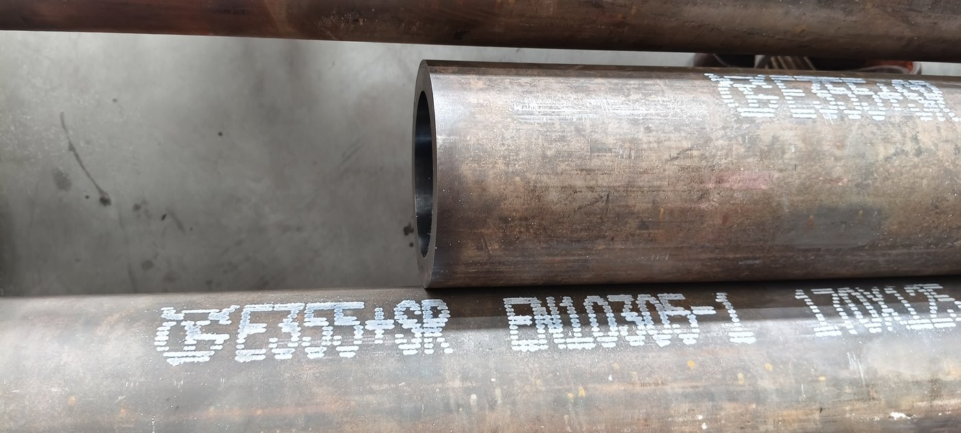
Verifying an MTR takes about two minutes and is worth doing. Three checks cover most of the risk. The heat number on the certificate must match the heat number stencilled on the tube or on the bundle tag. The reported values must be actual measurements, not the specification limits restated. And the issuing entity must be independent of production, which is what distinguishes 3.1 from a workshop report.
9. Selection by application
The fastest route to a correct specification is to start from the application and work backwards. The combinations below cover the majority of CDS demand.
| Application | Standard | Grade and condition | Bore and surface | Key inspection |
|---|---|---|---|---|
| Hydraulic cylinder barrel | EN 10305-4 | E355, +SR | Honed, Ra 0.4 µm, H8/H9 | Hydrostatic, dimensional 100% |
| Piston rod / chrome plated shaft | EN 10305-1 | E355, +SR | Peeled or ground OD, ready for plating | Straightness, OD tolerance, surface |
| Automotive shock absorber reservoir | EN 10305-1 | E235 or E355, +SR | As-drawn bore, oiled | Wall uniformity, ovality |
| Heat exchanger tube | ASTM A179 / EN 10216-2 | Low carbon, annealed | Pickled, capped | Eddy current 100%, flattening, flaring |
| Machined ring or roller blank | ASTM A519 | 4140 or 4145, Q&T | As-drawn or machined | Hardness, UT for heavy section |
| Pneumatic line | EN 10305-4 | E235, +N | Degreased, capped, optional zinc or epoxy | Cleanliness, pressure |
| Precision mechanical component | EN 10305-1 | E235 or E355, +N | Pickled, oiled | Tensile, dimensional |
| Boiler or high temperature service | EN 10216-2 | P235GH, 16Mo3 | Pickled, plain end | Per pressure equipment directive |
Note the last row. Boiler and high temperature service is outside the scope of EN 10305-1 entirely, because that standard does not specify elevated temperature properties. A tube that is dimensionally perfect to EN 10305-1 is the wrong document for a boiler application. This is one of the few cases where the standard selection, not the grade, is the critical error.
10. How to write an RFQ that gets an accurate quote
Most inaccurate quotations are not commercial decisions. They are the supplier’s best guess at an incomplete requirement. The specification below, completed, removes almost all of the guesswork.
| Item | What to state | Example |
|---|---|---|
| Standard and year | Full designation, not the trade name | EN 10305-1:2016 |
| Grade | EN designation plus any legacy equivalent on the drawing | E355 (St52.4) |
| Delivery condition | EN symbol | +SR |
| Dimensions | OD × wall × length, and whether length is exact or random | 63.5 × 5.0 × 6000 mm exact |
| Tolerances | OD, wall, straightness, and the measurement method for straightness | OD ±0.10, wall ±7.5%, 0.5 mm/m mid-span |
| Bore condition | As-drawn, honed with Ra, or roller burnished | Honed Ra 0.4 µm, H9 |
| Surface | Pickled, phosphated, oiled, or bare | Pickled and oiled |
| Tests | Which tests, at what frequency | Tensile per heat, ET 100%, hydrostatic 1.5 × design |
| Certificate | EN 10204 level | 3.1 |
| Marking and packaging | Heat number, standard, grade, bundle or crate | Stencilled, wooden crates, end caps |
| Quantity and delivery | Tonnes or pieces, required date, Incoterm | 24 t, CIF Hamburg, week 8 |
An RFQ that says “cold drawn seamless tube, 60 mm, 5 mm wall, 6 m, quantity 20 tonnes” will produce four quotations that cannot be compared, because each supplier will have assumed a different grade, condition, tolerance and inspection level. The cost of tightening the specification is one hour. The cost of resolving a mismatch after delivery is a rejected shipment.
If the application is unusual, or the drawing predates the current standard, send the drawing and state the service condition rather than the tube specification. A mill that understands the duty can propose the specification, and that proposal is easier to verify than a silent assumption. Our cold drawn seamless CDS tube range covers OD 6 to 380 mm with the conditions described above, and the wider cold drawn steel tube range includes welded and cold sized alternatives where the duty allows them.
Frequently asked questions
What is the difference between CDS and DOM tubing?
CDS is drawn from a seamless hot pierced mother tube, so it has no weld seam anywhere in its length. DOM is drawn from an electric resistance welded tube over a mandrel; the weld is normalised after drawing but remains a metallurgical discontinuity. DOM offers better wall uniformity and lower cost at volume. CDS is preferred for pressure, fatigue and corrosive duty, and for thick wall sizes where welded mother tube is not available.
Is DIN 2391 still a valid specification?
The standard was withdrawn and superseded by EN 10305-1. Drawings still cite it, and tube can legitimately be supplied against the old designation where the purchase order says so, but new orders should reference EN 10305-1 with an explicit tolerance class. The grade mapping is St30.4 to E215, St35.4 to E235 and St52.4 to E355.
What does +SR mean on a tube order?
Cold drawn and stress relieved. After the final drawing pass the tube is heated to a temperature below the transformation range in a controlled atmosphere, which removes most of the residual stress without significantly reducing strength. It is the usual condition for tube that will be machined to close tolerance, honed, or welded.
Can cold drawn seamless tube be welded?
Yes, but not in condition +C. Welding a hard, highly stressed tube produces a hardened heat affected zone sitting in a tensile stress field, which is the classic setup for delayed cracking. Specify +SR or +N for any tube that will be welded, and state the welding process so that the carbon equivalent can be checked against the grade.
What tolerance can cold drawn tube actually hold?
±0.05 mm on outside diameter is achievable below about 30 mm OD with a wall ratio above 6%, in condition +SR or +A. Above 90 mm OD, ±0.15 mm is the realistic commercial figure. Wall tolerance is normally ±10% as standard and ±5% as precision. Any quotation offering ±0.05 mm across a full size range is worth questioning.
Is EN 10305-4 better than EN 10305-1?
Neither is better; they cover different scopes. Part 4 applies to hydraulic and pneumatic power systems and adds bore cleanliness and pressure integrity requirements. Part 1 is the general precision tube standard. Ordering part 4 for a mechanical application adds cost without benefit; ordering part 1 for a hydraulic cylinder omits tests the circuit requires.
What is the HS code for cold drawn seamless tube?
Seamless circular tube of non-alloy steel, cold drawn or cold rolled, is classified under 7304.31. Alloy steel cold drawn seamless tube falls under 7304.51. The correct code depends on the actual grade chemistry and on the importing country’s tariff schedule, so it should be confirmed with the freight forwarder before the commercial invoice is issued.
What is the difference between cold drawn and cold rolled tube?
Cold rolling produces strip and sheet, and welded tube made from cold rolled coil. Seamless tube is produced by cold drawing, where the tube is pulled through a die. A drawing that specifies “cold rolled seamless tube” contains a contradiction and should be clarified before quotation.
What lengths can cold drawn seamless tube be supplied in?
Random lengths of 3 to 7 m are standard for EN 10305-1. Exact lengths up to 12 m are available, with tolerance of +10/0 mm as normal and ±1 mm achievable on cut-to-length orders. Longer lengths require negotiation because straightness and handling limits become the constraint rather than the mill’s capability.
How do I verify a mill test certificate?
Three checks. The heat number on the certificate must match the marking on the tube or bundle. The reported values must be actual measured results rather than the specification limits restated. And for a 3.1 certificate, the issuing function must be independent of production, which is stated on the document. Any certificate where all three cannot be confirmed should be treated as unverified.
Send the duty, not just the dimensions. If you are working from a legacy drawing, a drawing that cites DIN 2391, or an application where the delivery condition is still open, send the drawing and describe what the tube has to survive. We will come back with the standard, grade and condition that actually meet the requirement, together with the inspection scope needed to prove it.